Jetson Nano PWM配置
Updated on 7 Feb, 2021. For English User, there is an English version of this post. Link: https://www.seeedstudio.com/blog/2020/05/27/configure-pwm-output-on-jetson-nano-m/. By the way, I sincerely hope the translator will be capable of understanding the meaning of reference thoroughly next time.
最近要用PWM信号控制激光雷达的转速,一开始以为用Jetson Nano的PWM控制非常简单,结果看到了下面这段话
See
samples/simple_pwm.pyfor details on how to use PWM channels.
The Jetson.GPIO library supports PWM only on pins with attached hardware PWM controllers. Unlike the RPi.GPIO library, the Jetson.GPIO library does not implement Software emulated PWM. Jetson Nano supports 2 PWM channels, and Jetson AGX Xavier supports 3 PWM channels. Jetson TX1 and TX2 do not support any PWM channels.
The system pinmux must be configured to connect the hardware PWM controlller(s) to the relevant pins. If the pinmux is not configured, PWM signals will not reach the pins! The Jetson.GPIO library does not dynamically modify the pinmux configuration to achieve this. Read the L4T documentation for details on how to configure the pinmux.
大概意思就是说,要用硬件PWM就得改Pinmux,要用软PWM,抱歉,我们没写这个代码
官方参考代码
官方给出了PWM的Python参考代码
1 | import RPi.GPIO as GPIO |
GPIO.PWM的50是指代PWM频率,传闻上限是50kHZ p.start的25当然是指占空比了,范围是0-100
导出DT文件
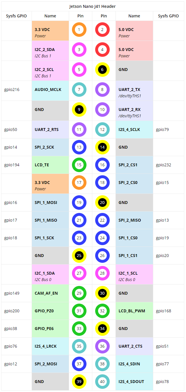
官方样例钦定了33作为PWM Pin,Jetson Nano的33 Pin实际上是GPIO_PE6,也就是说我们需要把GPIO_PE6配置为PWM
打开Jetson Nano Module Pinmux Config Template 下载链接,很轻松的就找到了GPIO_PE6
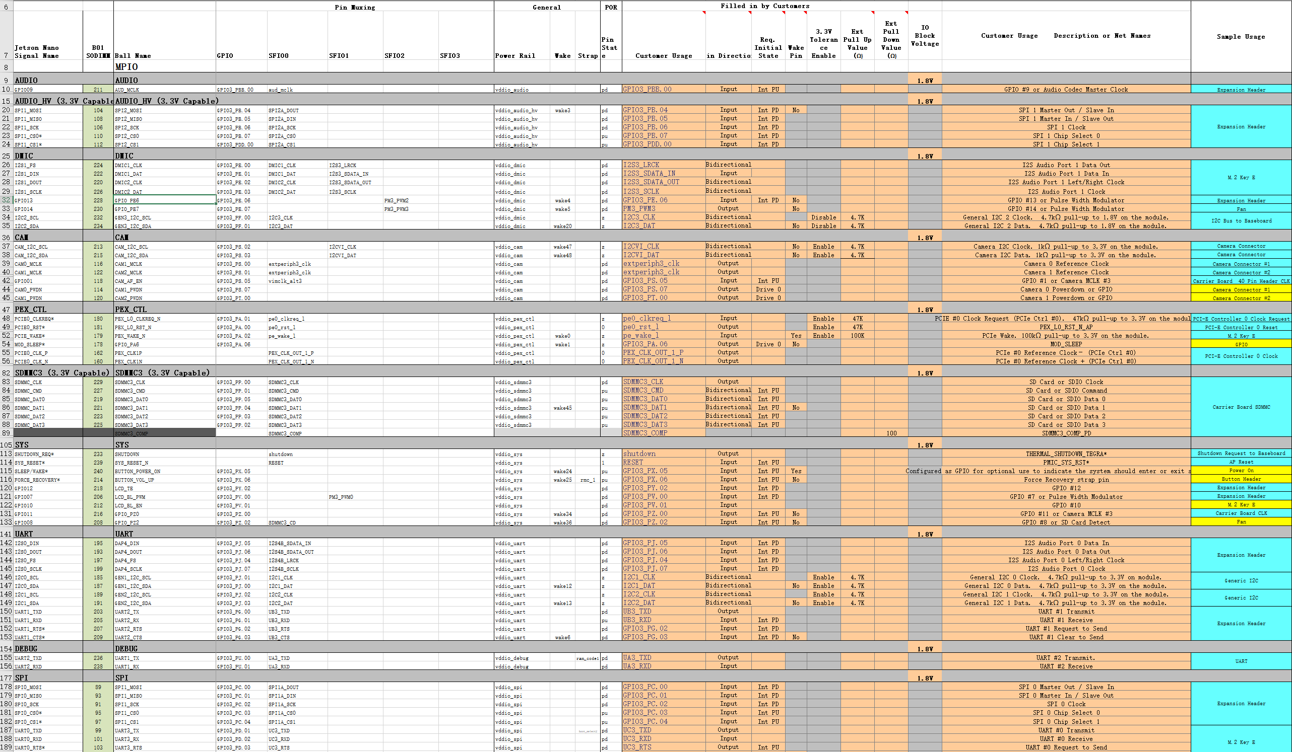
可见PE6可以配置为PM3_PWM2

然后这个Excel表格会提醒你改成输出模式(做表格的人真他娘的nb)
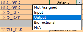
最后就可以Generate DT File了

期间,脚本会询问board name,输入jetson-nano-sd即可
最后将该Excel表格另存为CSV UTF-8 (comma-delimited) (*.csv)格式,文件名为jetson-nano-sd.csv
我们就得到了三个文件,把这个文件复制到电脑的Linux系统上
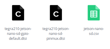
疯狂下载
参考文章: - NVIDIA Jetson Nano Pinmux官方文档
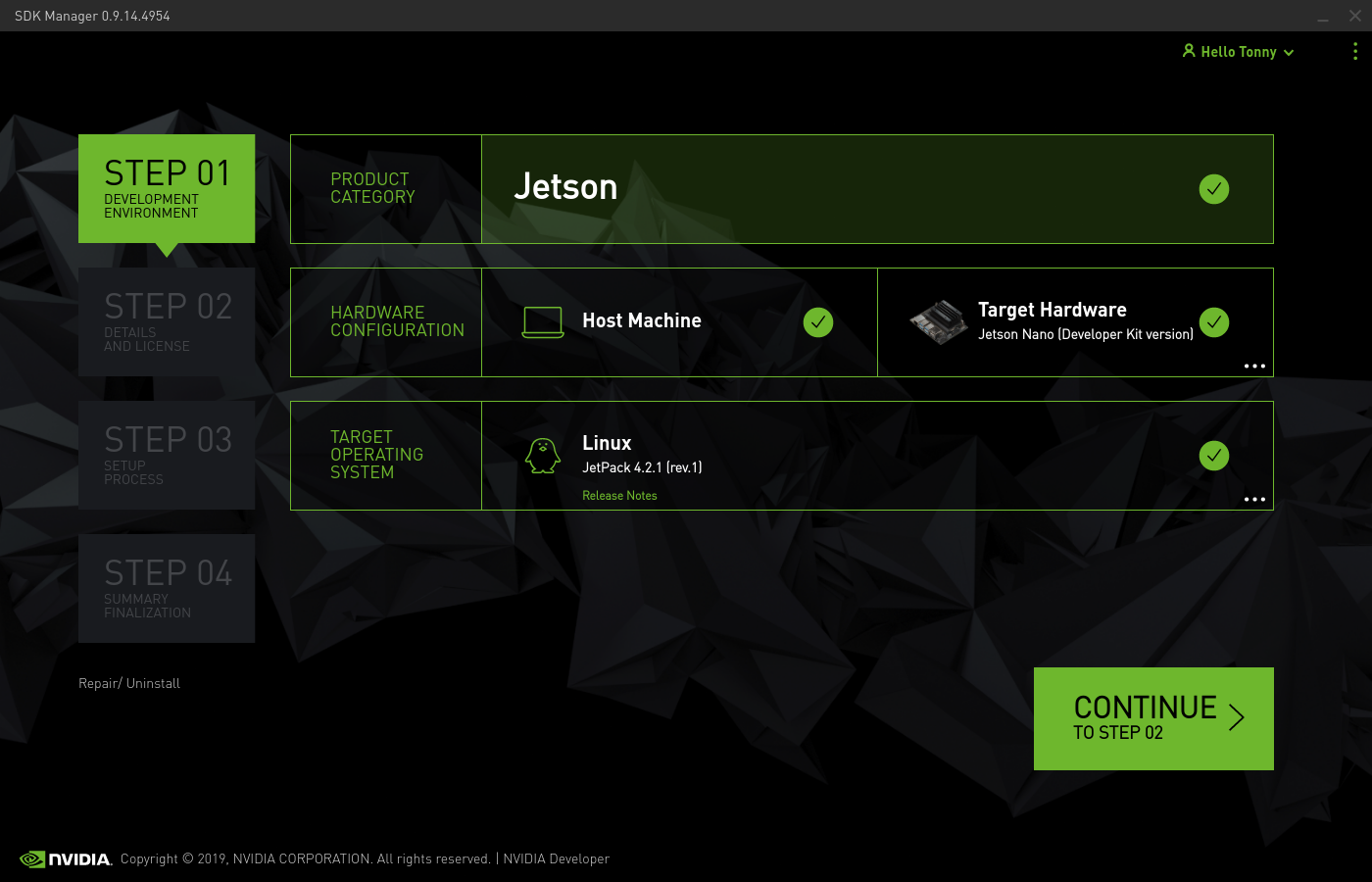
首先在SDK Manager下载Jetson Nano的全家桶,过程略
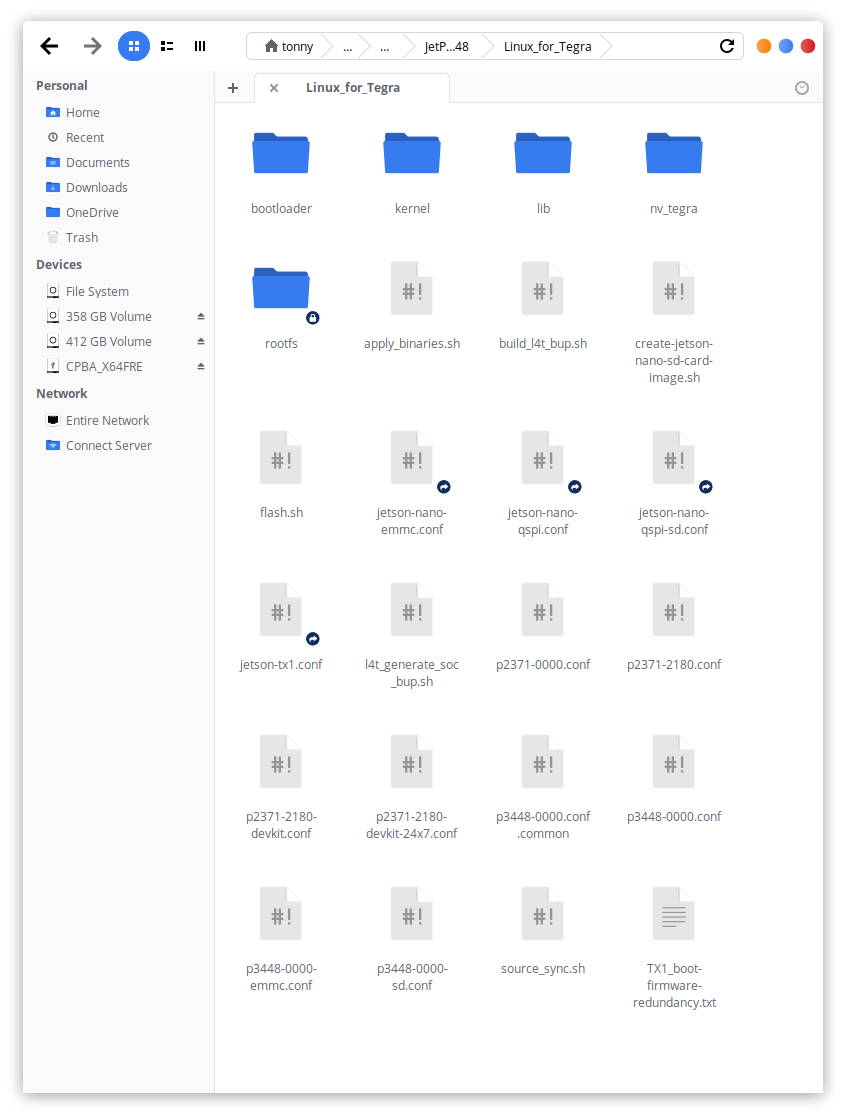
一切妥当后,在~/nvidia/nvidia_sdk/JetPack_4.2.1_Linux_GA_P3448/Linux_for_Tegra这个路径下应该能看到source_sync.sh
在终端下执行以下命令就可以把内核代码扒拉下来了 1
2sudo apt install build-essential bc bzip2 xz-utils git-core vim-common
./source_sync.shtegra-l4t-r32.2.0,这个tag要和其他东西的版本保持一致
然后我们就可以下载工具链了 下载工具链
建议勾选Filter
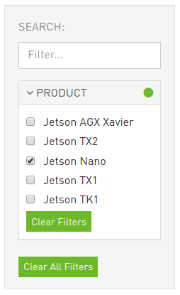
然后下载GCC Tool Chain for 64-bit BSP

随便解压一下工具包,并记住路径
比如我的路径就是/home/tonny/bin/gcc-linaro-7.3.1-2018.05-x86_64_aarch64-linux-gnu
编译Uboot
在Linux系统上下载脚本tegra-pinmux-scripts
1 | https://github.com/NVIDIA/tegra-pinmux-scripts |
在tegra-pinmux-scripts目录下创建csv文件夹,把之前得到的csv文件复制到里面去 1
2
3cd tegra-pinmux-scripts
mkdir csv
cp <path-to-csv>/jetson-nano-sd.csv csv/p3450-porg.csv
然后执行以下命令 1
2./csv-to-board.py p3450-porg
./board-to-uboot.py p3450-porg > pinmux-config-p3450-porg.h
用得到的pinmux-config-p3450-porg.h覆盖uboot目录/home/tonny/nvidia/nvidia_sdk/JetPack_4.2.1_Linux_GA_P3448/Linux_for_Tegra/sources/u-boot/board/nvidia/p3450-porg原来的文件
再设置环境变量,导入工具链的相关信息 1
export CROSS_COMPILE=/home/tonny/bin/gcc-linaro-7.3.1-2018.05-x86_64_aarch64-linux-gnu/bin/aarch64-linux-gnu-
安装dtc 1
apt-get install device-tree-compiler
退回到uboot源码根目录/home/tonny/nvidia/nvidia_sdk/JetPack_4.2.1_Linux_GA_P3448/Linux_for_Tegra/sources/u-boot,编译uboot
1 | make distclean |
最后将刚编译好的uboot导入L4T tree 1
cp u-boot.bin ../../bootloader/t210ref/p3450-porg/
更新CBoot
首先我们要检查自己的Jetson Nano的设备树版本
在nano上运行 1
cat /proc/device-tree/nvidia,dtsfilename
比如我的nano是tegra210-p3448-0000-p3449-0000-b00.dts,说明我们之后要修改b00版的文件,有的人可能拿到了a02版的nano,他们要改a02版的文件

如果L4T版本为32.1,需要去参考NVIDIA Jetson Nano Pinmux官方文档更新部分源码
回到Linux主机上,用之前Excel表格生成的dtsi文件覆盖源码里的文件
1 | $ cd Linux_for_Tegra/sources/hardware/nvidia/platform/t210/porg/kernel-dts/porg-platforms/ |
进入Linux_for_Tegra/sources/kernel/kernel-4.9/文件夹构建device tree image
1 | cd Linux_for_Tegra/sources/kernel/kernel-4.9/ |
最后将刚编译好的device tree image导入L4T tree
1 | cp arch/arm64/boot/dts/tegra210-p3448-0000-p3449-0000-<nano-dt-version>.dtb ../../../kernel/dtb/ |
刷机
在Linux_for_Tegra文件夹下执行
1 | sudo ./create-jetson-nano-sd-card-image.sh -o sd-blob.img -s <sd_card_size> -r <nano-dt-revision> |
注意,sd_card_size为sd卡大小,而nano-dt-revision与nano-dt-version的对应关系如下
| DT-Ver | DT-Rev |
|---|---|
| a01 | 100 |
| a02 | 200 |
| b00 | 300 |
这里我的sd卡为32g,dt-ver为b00,那么我实际执行了
1 | sudo ./create-jetson-nano-sd-card-image.sh -o sd-blob.img -s 32G -r 300 |
下一步,进入目录Linux_for_Tegra/bootloader/signed,将对应版本的tegra210-p3448-0000-p3449-0000-<nano-dt-version>.dtb.encrypt复制到nano上
然后在nano上执行 1
sudo dd if=tegra210-p3448-0000-p3449-0000-<nano-dt-version>.dtb.encrypt of=/dev/disk/by-partlabel/DTB
当然个人建议先备份一下,万一失败了还能抢救一下 1
sudo dd if=/dev/disk/by-partlabel/DTB of=backup.dtb.encrypt
附录
进入Force Recovery Mode的方法: nano-dev-kit-user-guide
- Jumper the Force Recovery pins (3 and 4) on J40 button header
- Jumper the J48 Power Select Header pins and connect a power supply to J25 power jack. The developer kit automatically powers on in Force Recovery mode.
- Now that the developer kit is running, remove the Force Recovery pins’ jumper.

其实短接Recovery pins就可以了,不一定要用DC接口,只要能保证供得上电就行,比如在40pin引脚的5v上加个电源